|
|
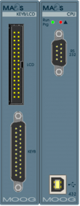
Module IMI220-432A001/B001 is a double module (occupies two card slots) consisting of a main process section and by a video section.
Main process section activities can be sub-divided in two types:
- basic software run (operating system);
- user-written program run.
On the module there is a HCMOS, 32-bit microprocessor performing execution of an elementary instruction on a variable (LD, AND, OR, ST) in 240 nanoseconds, while elementary instructions on registers are executed in 95 nanoseconds.
The video section can control a monochrome LCD display (VGA) in graphical mode, therefore it is possible to display graphs and synoptic drawings; it is also possible to connect a local matrix keyboard locale (lines x columns) provided with max 88 keys and 64 led the keyboard may be either a 400 series matrix keyboard or a custom keyboard made in accordance with specifications from Moog.
On the same rack there cannot be mounted more than one module IMI220-432A001/B001/D001, nor any other main processor module.
Maximum allowed length for display cable is 3 m.
Maximum allowed length for matrix keyboard cable is 3 m.
Module IMI220-432A001 CANNOT be placed beyond card slot # 16.
Module Specifications
|
Main processor Section |
|
|
Microprocessor |
32-bit in HCMOS technology (@ 20 MHz) |
|
Processing time |
|
|
- binary operation |
internal 95 ns |
| external 240 ns | |
|
Memory Type |
|
|
- RAM (total) |
|
|
IMI220-432A001 (with IMI220-400A001) |
256 kbyte static (stand by from power supply) |
|
IMI220-432B001 (with IMI220-400B001) |
1 Mbyte static (stand by from power supply) |
|
- Flash-EPROM (total) |
1 Mbyte |
|
- Flash-EPROM (user) |
> 512 Kbyte |
|
Cycle Time |
user-programmable (in integer multiples of 2 ms) |
|
Programming Languages |
IL, LD, ST, according to IEC1131-3 |
|
Data Memories |
|
|
- referred to I/O modules (max) |
64 Kbyte |
|
- global variables (max) |
64 Kbyte |
|
Count Functions (function block) |
|
|
- timers |
|
|
times base |
integer multiples of cycle time |
|
associated variables |
timer value, startup delay, shutdown delay, impulse timer |
|
- counters |
|
|
count range |
-32768...32767 (forwards / backwards |
|
associated variables |
counter value, counter=0, counter>=set |
|
Number of digital inputs / outputs |
|
|
- theoretical |
10000 |
|
Number of analog inputs / outputs (max) |
112 |
|
Clock calendar |
h/min/sec, year/month/day |
|
Logical instructions list |
AND, OR, LD, ST, ANDN, ORN, LDN, STN, S, R |
|
Functions list |
> 100 |
|
Interfaces |
RS232, parallel |
|
Operating Temperature |
|
|
- in vertical position |
0...60° C |
|
- in horizontal position |
0...40° C |
|
Operating Diagnostics |
|
|
- halt |
red led |
|
- run, prog |
green led (on = run, blinking = PLC prog.) |
|
Supply current |
|
|
- typical (+5 V) |
250 mA |
|
- stand by |
1 µA |
|
Insulation |
no |
|
Front Connectors |
|
|
- RS232 |
type D 9 pins M |
|
- parallel |
type D 25 pins M |
|
Cables Section |
|
|
- RS232 |
0.14...0.5 mm² |
|
- parallel |
0.14...0.5 mm² |
|
Cable length for communications |
|
|
- RS232 (max) |
15 m |
|
- parallel |
2 m |
|
Video Section |
|
|
Visualization type |
monochrome in graphical mode |
|
Video resolution |
640 x 480 pixel (80 x 30 car.) |
|
External display |
LCD B/W (VGA) |
|
External keyboard |
|
|
- type |
passive max 88 key, max 64 led |
|
- configuration |
matrix 11 col., 8 rig. |
|
- input current |
1 mA @ 5 V |
|
- debouncing |
software |
|
Front Connectors |
|
|
- display |
34 pins M, with central polarization |
|
- keyboard |
type D 25 pins M |
|
Cables Section |
|
|
- display |
flat cable 28 AWG |
|
- keyboard |
0.14...0.5 mm² |
|
Cable length |
|
|
- display (max) |
3 m |
|
- keyboard (max) |
3 m |
|
General Specifications |
|
|
Operating Temperature |
|
|
- in vertical position |
0...60° C |
|
- in horizontal position |
0...40° C |
|
Dimensions L x H x D (mm) |
50 x 130 x 95 |
|
Weight |
0.290 Kg |
Main Processor Section
- Red LED (Halt): if on, indicates a hardware problem (processor in HALT);
- Green LED (Run, Prg): if the module is in RUN this led is always on; when programming the PLC this led blinks at a frequency of about 1.6 Hz; if the PLC is not operating (BOSS) it led blinks at a frequency of about 1 Hz;
- 25 pin connector: is used to connect Series 400 PLC to the personal computer used for la programming or for remote control;
- USB connector: used to connect the Series 400 PLC to the personal computer used for the programming or remote control.
- 9 pin connector: is used to connect Series 400 PLC to intelligent graphical terminals;
Video section
- 34 pin connector: is used to connect an LCD VGA B/W display;
- 25 pin connector: is used to connect the matrix keyboard.